Copy and share this link on social network or send it to your friends
Copy| Product Name | 433MHz /510MHz /868MHz /915MHz/ Lora Signal Booster Transmitting & Receiving Two-Way Power Amplifier Signal Amplification Module |
| Item NO. | F45892-D1 F45891-D1 F46475 F45891-D2/1 F45892-D2 |
| Weight | 0.05 kg = 0.1102 lb = 1.7637 oz |
| Category | DIY RC Drone Accessories > VTX |
| Creation Time | 2022-01-24 |
Note: AB-IOT-868MHz Patch & AB-IOT-868MHz SMA will not continue to be produced. Customers who need it can check the upgraded version. Here is the link: https://www.xt-xinte.com/h-product-detail .html?goods_id=960718
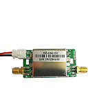
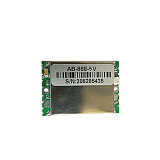
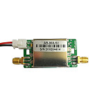
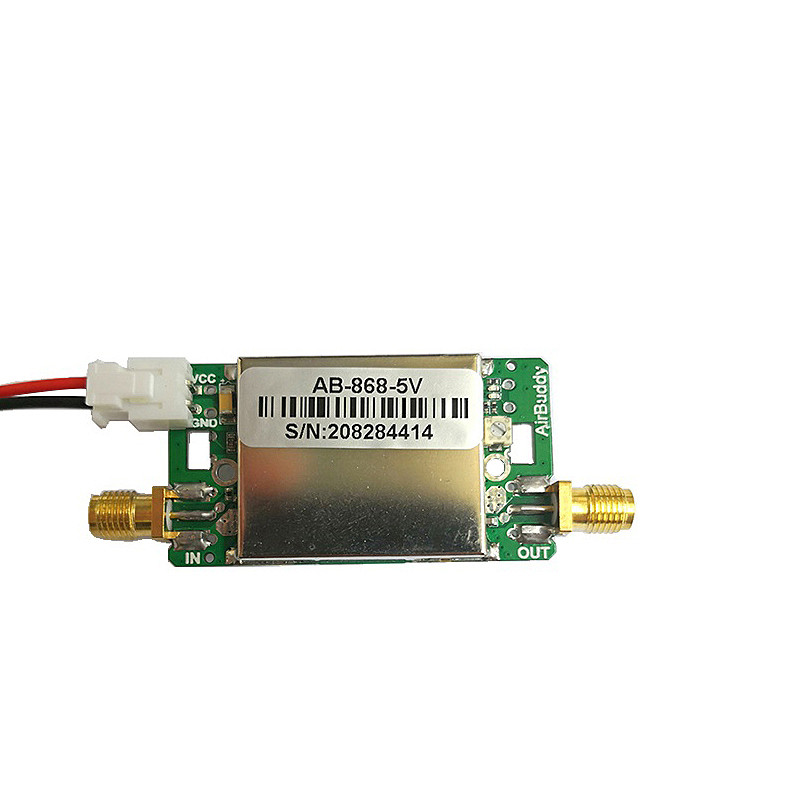
There are Patch modules and SMA modules option!
Purchase notice:
(AB-IOT series amplifier is an upgraded version of XQ-433, with a wider range of power supply voltage, please refer to the manual carefully before purchasing, or consult customer service, thank you!):
* The applicable frequency bands of "AB-IOT-433" and "AB-IOT-433-SMA" are: 420MHz-480MHz;
The applicable frequency bands of "AB-IOT-510" and "AB-IOT-510-SMA" are: 470MHz-520MHz;
The applicable frequency bands of "AB-IOT-868" and "AB-IOT-868-SMA" are: for Europe 863MHz-870MHz;
The applicable frequency bands of "AB-IOT-915" and "AB-IOT-915-SMA" are: for America 902MHz-928MHz;
1. The product is a two-way amplified TDD working mode (that is, the transmit power and receiving sensitivity will be amplified equally);
2. The working voltage is 3.6V-6V;
3. This product is highly professional, and wireless communication is greatly affected by the environment. We only guarantee that all parameters are measured by the instrument.
Description:
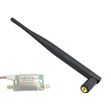
AB-IOT-433/AB-IOT-510 series two-way signal amplification modules are designed for various applications in the 433MHz (420MHz-480MHz) and 510M (470MHz-520MHz) frequency bands. Its compact size and convenient use make it easier to design products for high-power and long-distance applications in this frequency band.
Mainly used in various occasions in the 400MHz-480MHz frequency band that have special requirements for signal transmission distance and connection stability, such as: 433MHz remote control aircraft, 433MHz wireless data acquisition system, Lora products, 470MHz-510MHz, etc. Working in the 400MHz-520MHz frequency band Micro-power wireless products within the range can use this two-way amplification module to increase the transmission distance.
(Note: Hand-held walkie-talkies cannot use this module to achieve the purpose of extending the transmission range due to their high transmission power.)
Performance characteristics
The built-in intelligent receiving/sending discrimination circuit does not require front-end equipment to provide receiving/sending switching control signals.
The module works in the receiving state by default and amplifies the received signal. When the front-end equipment is detected to transmit external signals, it will instantly switch to the transmitting and amplifying state.
The transmission gain is manually adjustable, which is convenient for compatible wireless devices with different transmission powers.
The receiving/sending link has a high degree of isolation, and the receiving link can withstand strong external interference without causing self-excitation of the loop.
Compatible with various modulation methods such as LORA and FSK/ASK/OOK/MSK/GFSK.
The default working frequency band is 420MHz-480MHz, and it can be applied to any frequency band between 300MHz-600MHz by adjusting the parameters (bandwidth 60MHz, such as 300MHz-360MHz, 520MHz-580MHz...), if you have such a requirement, please contact us .
parameter:
Working frequency band: 420MHz-480MHz;, 470MHz-520MHz
Receiving gain: 11dB±2dB
Receiving noise figure: ≤2.0dB
Transmission gain: 5dB – 11dB (±2dB) adjustable
Recognition threshold for receiving and sending switching: -2dBm
Input power range: 1dBm-25dBm
Maximum transmit power:
31.5dBm (1.4w) at 3.7V supply voltage
33.5dBm (2.3w) at 5.0V supply voltage
34.5dBm (2.8w) at 6.0V supply voltage
Work status indication:
Receiving status: green light is on, blue light is off
Transmitting status: blue light is on, green light is off
In TDD working mode, the blue light and green light will flash alternately
Operating Voltage:
The power supply voltage can be between 3.6V-6.0V.
The maximum transmission power increases as the supply voltage increases.
Working current:
RX status:
10mA (±3mA)
TX status:
≤800mA (3.7v power supply)
≤1000mA (5.0v power supply)
≤1500mA (6.0v power supply)
Patch module dimensions:
38.2mm*26.2mm*4.5mm(L*W*H)
Remarks:
The working voltage only affects the maximum transmission power, and has little effect on the transmission gain. Therefore, for applications where the output power of the front-end equipment is not large, it is generally recommended to use a 3.7V lithium battery for direct power supply or a 5.0V power supply, and it is not necessary to use a 6.0V power supply.
Since the maximum transmit gain of the module is about 11dB, if the actual output power of the module can reach the maximum, the output power of the front-end equipment must be sufficient. For example, if the actual output power reaches 34.5dBm when the power supply voltage is 6.0V, the front-end The output power of the device must reach 13.5dBm (23.5+11=34.5). If the output power of the front-end device is only 10dBm, even if the working voltage is 6.0V, the actual output of the module can only reach 21dBm instead of 34.5dBm. Please pay attention to this point.
Under normal circumstances, the maximum gain (power) transmission is not recommended, because the greater the transmission power, the greater the power consumption and heat generation. If the power consumption is large, it is extremely disadvantageous for battery-powered equipment. In actual use, it is recommended to adjust the gain while testing coverage Scope, so that it can just meet the actual coverage requirements and a slight surplus is better.
In order to ensure reliable switching, the transmit power of the front-end equipment needs to reserve at least 3dB margin, that is, the minimum transmit power of the front-end equipment cannot be lower than 1dBm, otherwise it may cause the instability of the receiving/transmitting switch.
When the module is working, most of the sequence is in the receiving state, and the current in the receiving state is about 10mA. When the module is switched to the transmitting state and transmitting at maximum power, the instantaneous current can reach up to 1.5A. Because the transmission sequence is generally very short (normally, each group of data packets is ms or even us level), so the average current is generally not higher than 200mA during the entire working period.
Warning: The module is not recommended for applications with constant emission (that is, the blue light is always on)! If it is necessary to work in constant transmission mode and the transmission power is high (close to 1.3w), there will be large current and serious heat generation. At this time, additional heat dissipation measures (such as adding a heat sink or fan) must be added, otherwise the maximum transmission power will be It will automatically decrease due to high temperature, and the amplifier module will be burnt in severe cases.
Transmission gain adjustment method:
The transmit gain when the potentiometer turns counterclockwise to the end is 5dB;
The transmission gain when the potentiometer is turned to the end is 11dB.
Module pin definition:


Email:yxy@xt-xinte.com
Wechat:15012645226
Microsoft teams: 13640955802


No related record found