
|
| Quantity | 0-3 | 4-50 | 51-100 |
| Discount | 0% OFF | 5% OFF | 10% OFF |
| Price | US$ 39.07 | US$ 37.12 | US$ 35.16 |
Copy and share this link on social network or send it to your friends
Copy| Product Name | FPV 1.2G 0.1mW/25mW/200mW/800mW 9CH Transmitter TX & Receiver RX FPV Combo for RC Models Drone Quad Enhancement Booster |
| Item NO. | F50777-D1 F50777-D2 F50777-D3 |
| Weight | 0.045 kg = 0.0992 lb = 1.5873 oz |
| Category | DIY RC Drone Accessories > Receiver |
| Creation Time | 2023-09-09 |
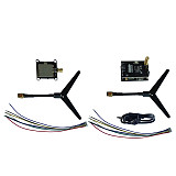
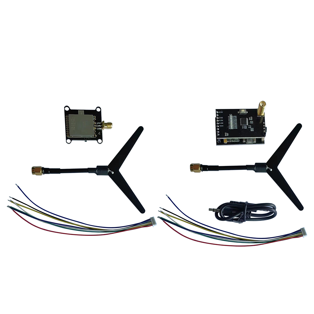
FPV 1.2G 0.1mW/25mW/200mW/800mW 9CH Transmitter TX & Receiver RX FPV Combo for RC Models Drone Quad Enhancement Booster
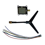
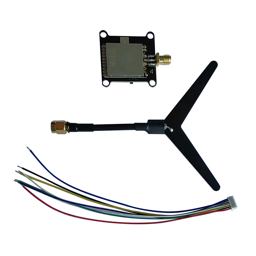
Transmitter:
I. Button control and LED indicators
1. Green indicator 4pcs are power indicators, they are: 0.1mW(0)/25mW(D)/200mW(C)/800mW(H).
(D)/200mW(C)/800mW(H), the default is 0.1mW when the power is on.
to the next power level. This operation can be cycled and the corresponding power indicator will light up every time you press and hold the button.
The corresponding power indicator will light up each time you press and hold the button. Note: The transmitting power must be readjusted after each power
failure.
II. The 9 red LEDs are frequency indicators.
This operation can be cycled, each short press on the corresponding frequency point indicator will light up.
Note: The operating system has a memory function, the system will save the current frequency point after power failure. II. Interface definition:
The antenna is SMA interface; the antenna head is "male thread + hole" and the antenna pole is "female thread + pin".
Pin" configuration 1.2G special customized "Y" type antenna.
2.7P1.25
The sequence of the socket connection is:
1. power input DC 7-28V;
2. input ground;
3. video input;
4. 6.5M audio input;
5. DC output 7-28V;
6. DC output ground;
7. DC output 5V.
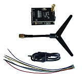
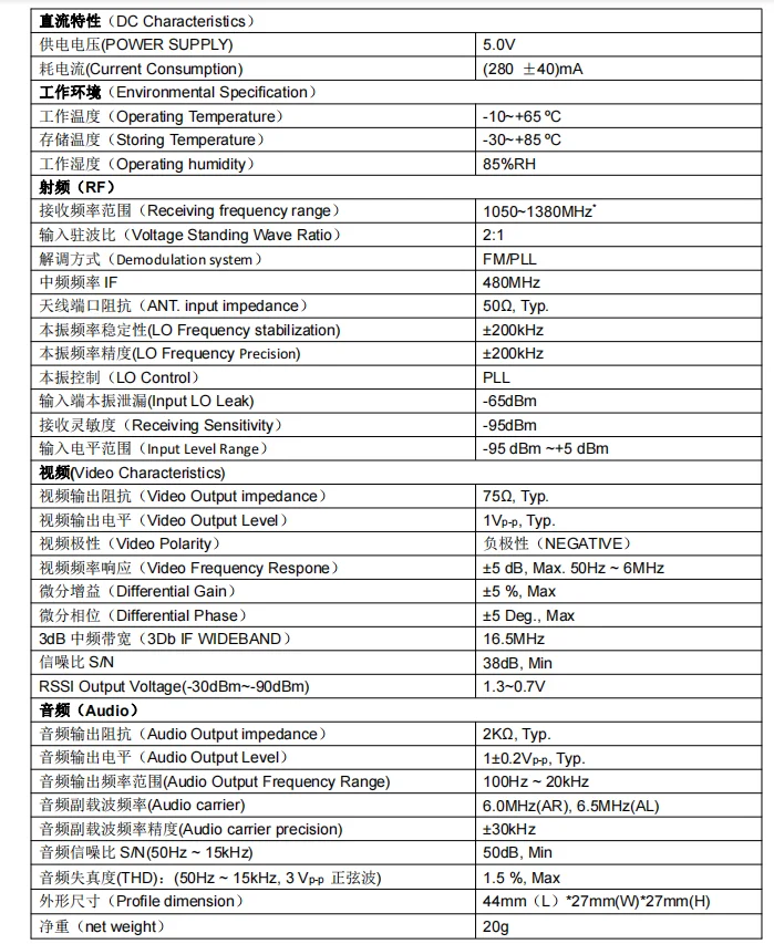
Receiver:
I: Button control and LED indicators
The 9 red indicators are the frequency point indicators and are switched to the next frequency point by pressing the button once.
This operation can be cycled, each short press of the corresponding frequency point indicator will light up.
Note: This operating system has a memory function, the system will save the current frequency point after a power failure.
II. Interface definition:
The antenna is SMA interface; the antenna head is "male thread + hole" and the antenna pole is "female thread + pin".
Pin" configuration 1.2G special customized "Y" type antenna.
3.7P1.25
The sequence of the socket connections is:
1. power input DC 7-28V;
2. input ground;
3. video input;
4. 6.5M audio input;
5. DC output 7-28V;
6. DC output ground;
7. DC output 5V.
III. Reserved 5P pads are defined in the following order:
1. power input DC 7-28V;
2. input ground;
3. video input;
4. DC output 5V;
5. DC output ground;


Email:yxy@xt-xinte.com
Wechat:15012645226


No related record found