| Quantity | 0-3 | 4-50 | 51-100 |
| Discount | 0% OFF | 5% OFF | 10% OFF |
| Price | US$ 48.45 | US$ 46.03 | US$ 43.61 |


Copy and share this link on social network or send it to your friends
Copy| Product Name | FEICHAO Wheel Program 10S ESC 36V Large Board Dual-Drive Board Upgraded Remote Control For Scooters/ Unicycles/Twist /Balance Cars |
| Item NO. | F45414 |
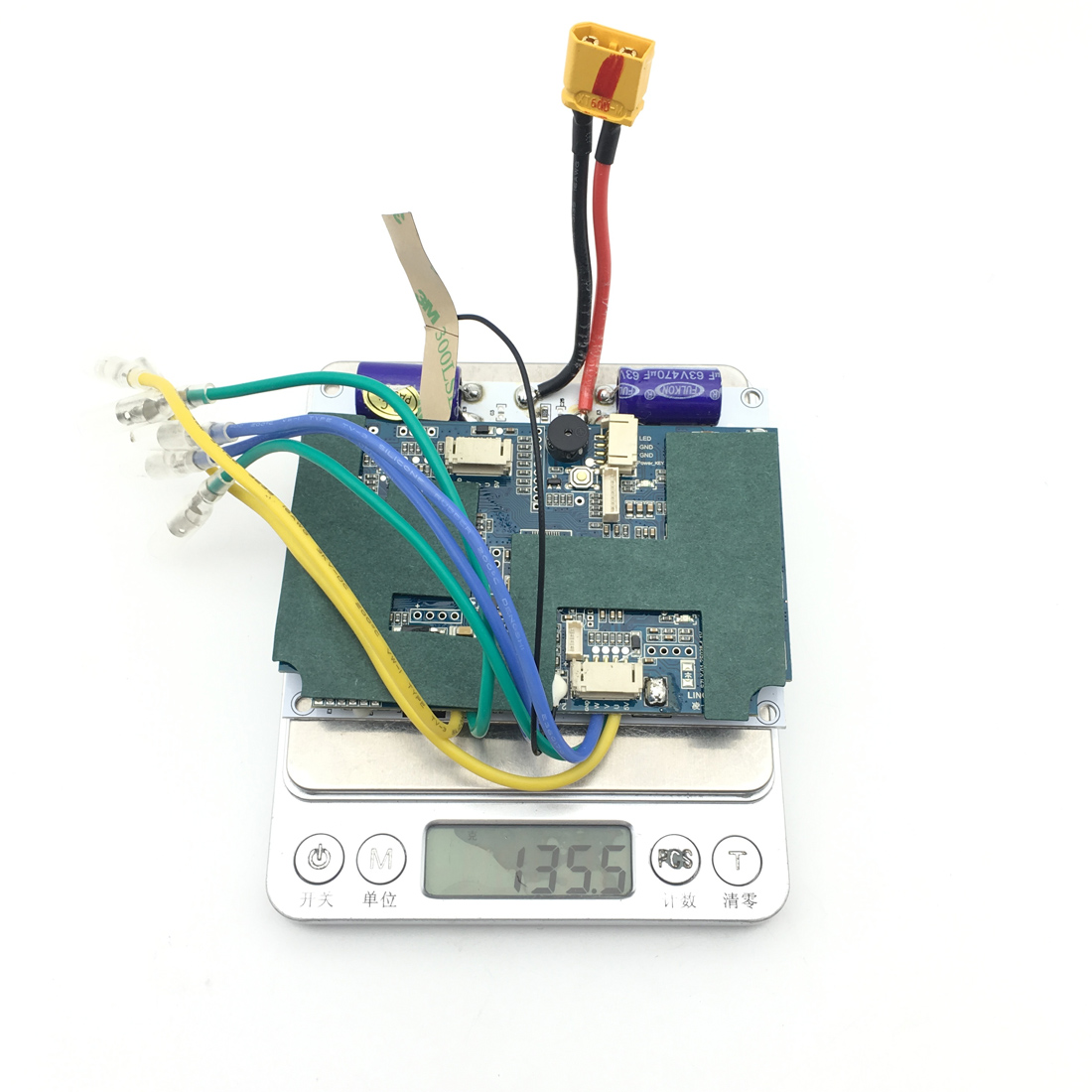
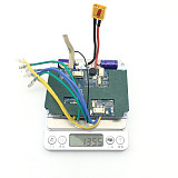
| Weight | 0.41 kg = 0.9039 lb = 14.4623 oz |
| Category | Toy and Hobbies > Remote Control Toys |
| Brand | FEICHAO |
| Creation Time | 2021-11-23 |
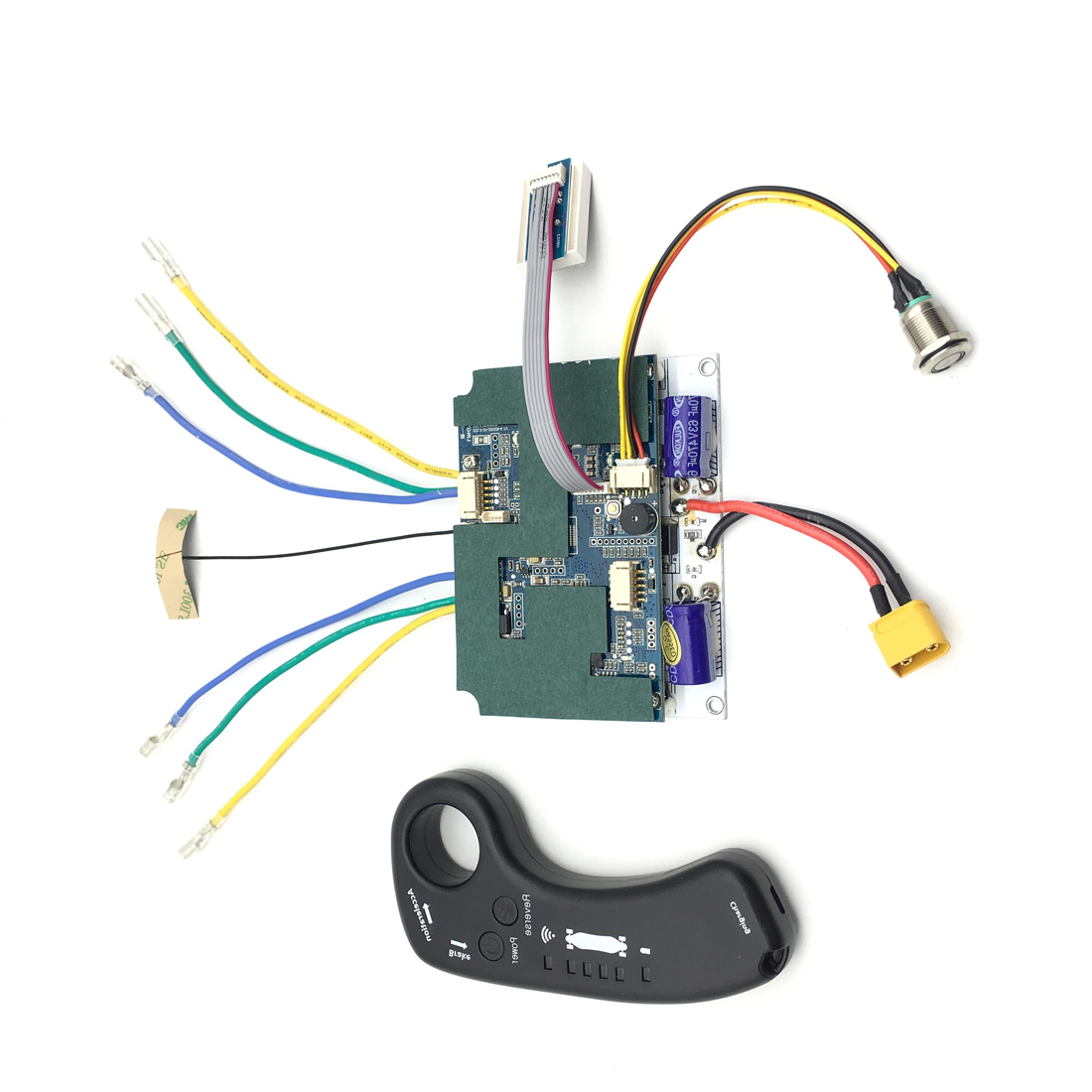
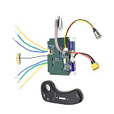
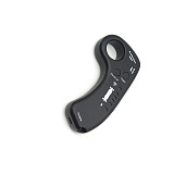
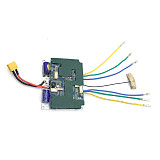
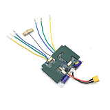
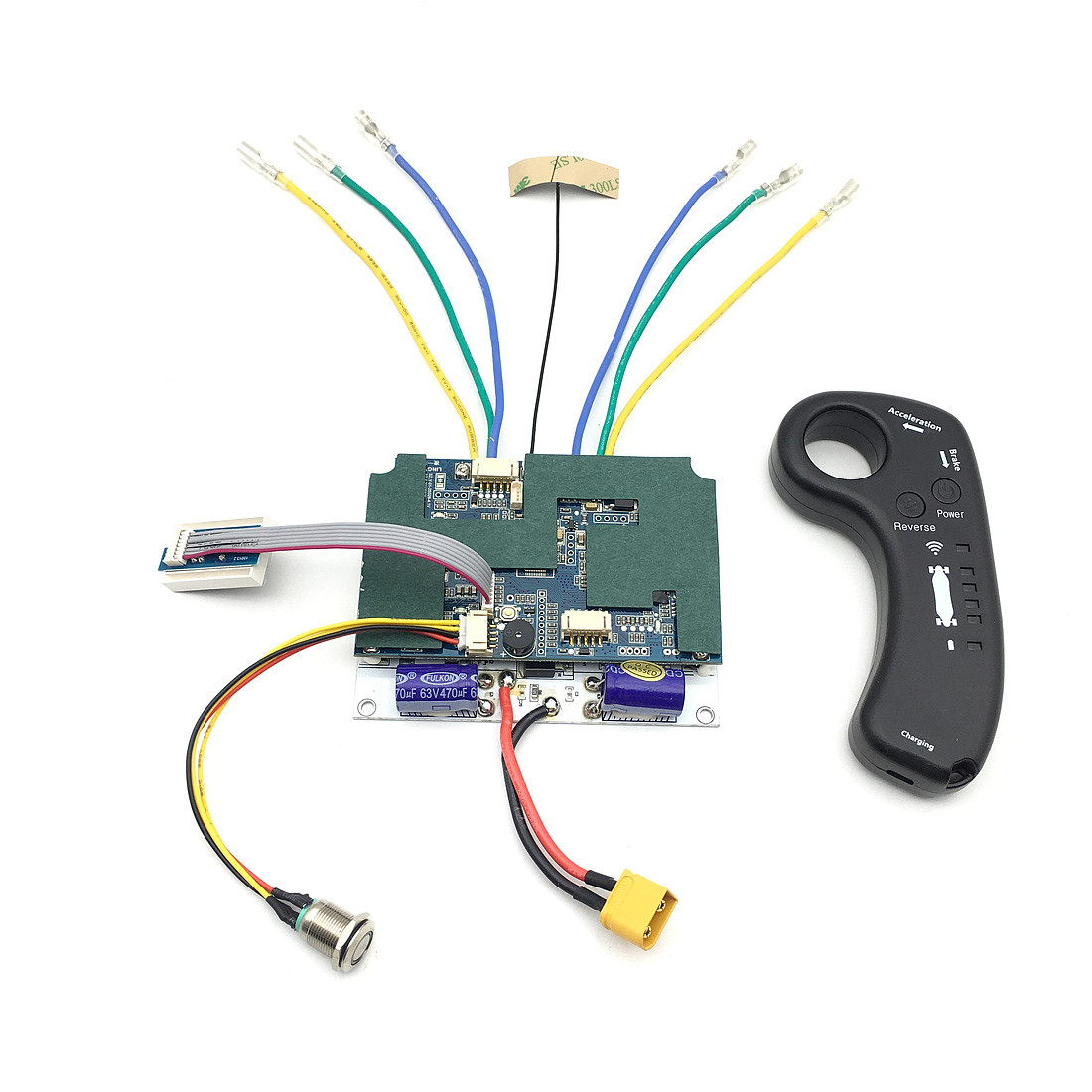
FEICHAO Wheel Program 10S ESC 36V Large Board Dual-Drive Board Upgraded Remote Control For Scooters/ unicycles/twist /balance cars
Controller type and performance;
Controller type: T2 wireless dual drive
Voltage range: DC 24/36V
Controller total power: 1300W
Number of control motors: 2
Type of control motor:
Motor type: DC brushless motor
Maximum motor power: within 650W
Maximum motor speed: within 8000 rpm
Can you not connect the motor Hall: Can you not connect
1 set contains:
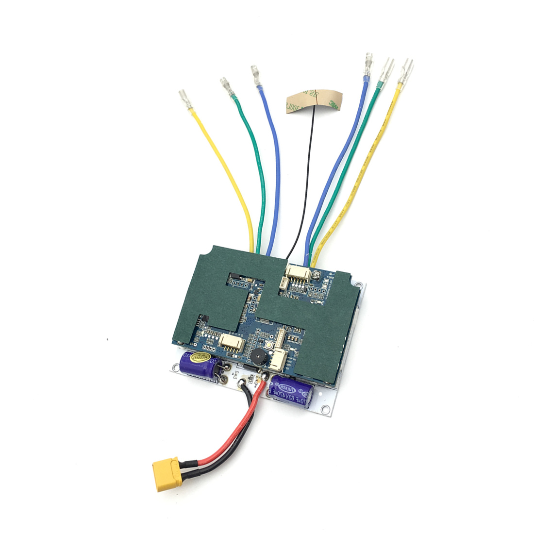
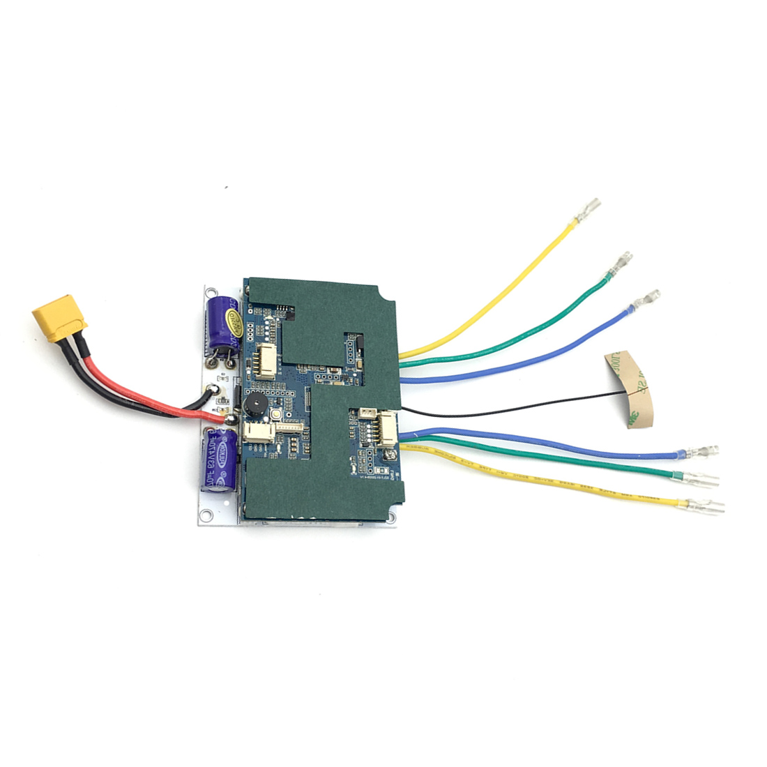
Main control board*1
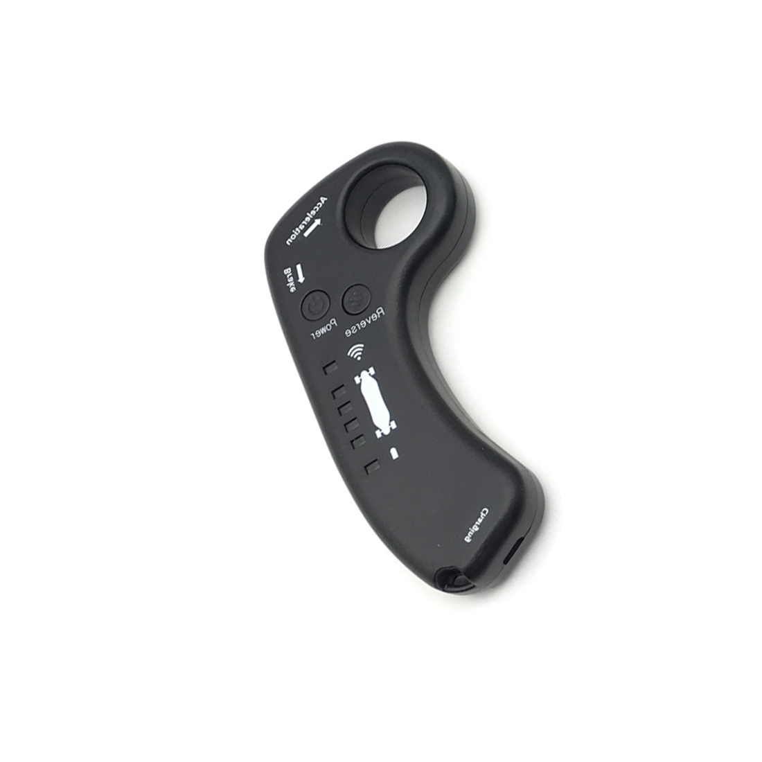
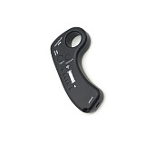
Remote control*1
Metal switch*1 (light touch type, with green light)
Power display*1
Packing box size: 200mm*110mm*40mm
How to choose the right controller:
1. Confirm the voltage of your battery
6 series battery is 25.2V, 7 series battery is 29.4V, 10 series battery is 36V
2. Confirm the motor type
External motor, chain, belt drive, use the controller with the word belt
Hub motor, motor integrated wheel, please select the controller with the word “hub”
3. Confirm single-drive dual-drive or four-wheel drive
A motor driven by a controller is a single drive
One controller drives two motors is dual-drive
One controller drives four motors is four-wheel drive
Taboo: Do not connect motor cables in parallel to allow single drive to drive two motors
Electric four-wheel skateboard control system:
Adopting the sine wave scheme, the performance is more stable than the ESC, and it is not easy to burn out
Features: low speed and high torque
Two-way communication, you can check the power of the skateboard through the remote control
Low-voltage alarm function, under-voltage power-off protection function
Note: Different voltage, alarm voltage, protection voltage are different
Carrying weight: ≤120KG
Application areas: scooters, unicycles, twist cars, balance cars
Suitable for hub motor model airplane motor 5055 5065 6354 6364 6374 6384
Description of matching signal between remote control and main controller:
1: Connect the main controller to the power supply
2: Turn on the power, wait for two seconds, then press and hold the key for about 6 seconds, let go when the switch indicator flashes
3: Turn on the remote control switch, and use a small screwdriver to press the button in the small hole in the lower left corner of the remote control.
4: Turn off the remote control and turn it on again for two seconds. Wait for the signal light of the remote control and the switch light to flash at the
same time to indicate that the configuration is successful!
About the motor Hall wire connection description:
At present, the normal version and standard version of the controller need to provide conventional connection methods for the phase sequence. The brushless
motor is controlled by 3 phases and 6 beats. Therefore, 3 Hall states correspond to 3 motor wires and 6 output states. There are 36 connections for different
combinations. Method, there are 6 ways to connect
The machine runs normally, and 3 of the 6 connections are forward rotation and the other 3 connections are reverse rotation. So it is necessary for us to
master the wiring rules.
One: First, we have to make the motor rotate normally, usually the Hall plug is directly plugged in to adjust the motor wire.
Here are 6 regular connection methods, there is always one that can make the motor run normally
1》Motor wire blue to controller blue, motor wire green to controller green, motor wire yellow to controller yellow
2》Motor wire blue to controller blue Motor wire green to controller yellow Motor wire yellow to controller green
3》Motor wire yellow to controller yellow Motor wire blue to controller green Motor wire green to controller blue
4》Motor wire green to controller green, motor wire blue to controller yellow, motor wire yellow to controller blue
5》Motor wire blue to controller yellow Motor wire yellow to controller green Motor wire green to controller blue
6》Motor wire yellow to controller blue Motor wire blue to controller green Motor wire green to controller yellow
Summarizing the above rules, we can compile a set of jingle to facilitate memory
Generally, the controller is placed on the top, and the motor is placed on the bottom. We can remember this
1 "color to color
2 "Blue to blue, the other 2 colors are reversed
3》Yellow to yellow, the other 2 colors are reversed
4 "Green to green, other 2 colors swapped
5 "Upper blue to lower blue, the other 2 colors are reversed
6 "Upper yellow to lower blue, the other 2 colors are reversed
Hall has positive and negative, indicating that the motor has a phase angle of 60°, and if there is no positive and negative, it is a 120° phase angle. You
can put them in as they are (you can use 502 instant glue to fix them), and connect the positive and negative poles of the three Halls in parallel with the
thin red and
The black wires are connected and welded (pay attention to insulation). Connect the three hall signal wires to the thin yellow, green and blue wires of the
motor lead wires and solder (pay attention to the insulation).
Two: The above connection can make the motor run normally, but not necessarily forward. If you want to adjust to the forward rotation, you can adjust the
motor wire A phase C relative to the Hall wire A phase B relative adjustment.


Email:yxy@xt-xinte.com
Wechat:15012645226


No related record found