


|
Copy and share this link on social network or send it to your friends
Copy| Product Name | Feichao DIY Kit D2-5 Intelligent Tracking Line Car Truck Suit Motor Electronic Assembly Smart Patrol Smart Automobile Accessories |
| Item NO. | F31317 |
| Weight | 0.05 kg = 0.1102 lb = 1.7637 oz |
| Category | Toy and Hobbies > Science Education Toy |
| Brand | FEICHAO |
| Creation Time | 2019-09-09 |
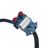
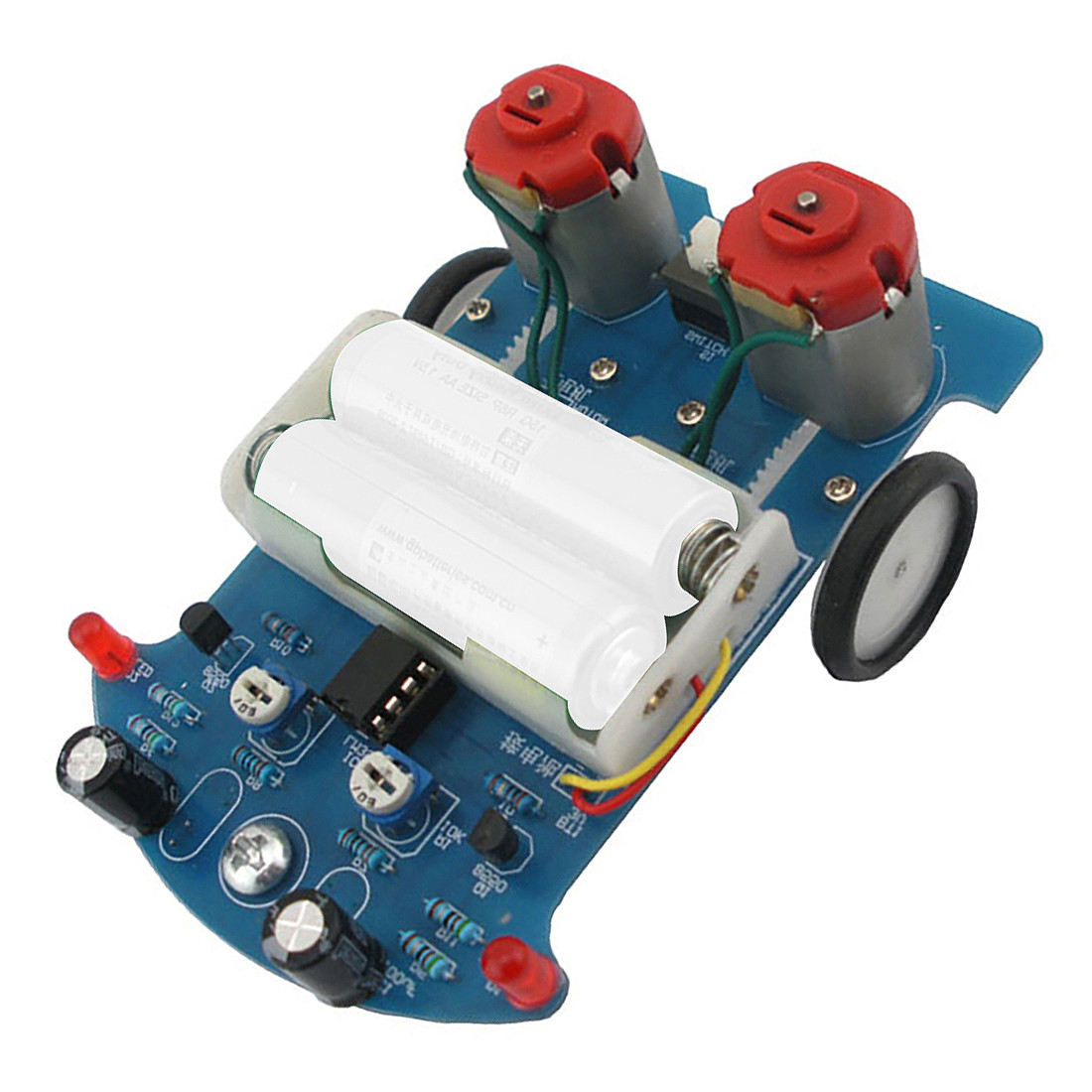
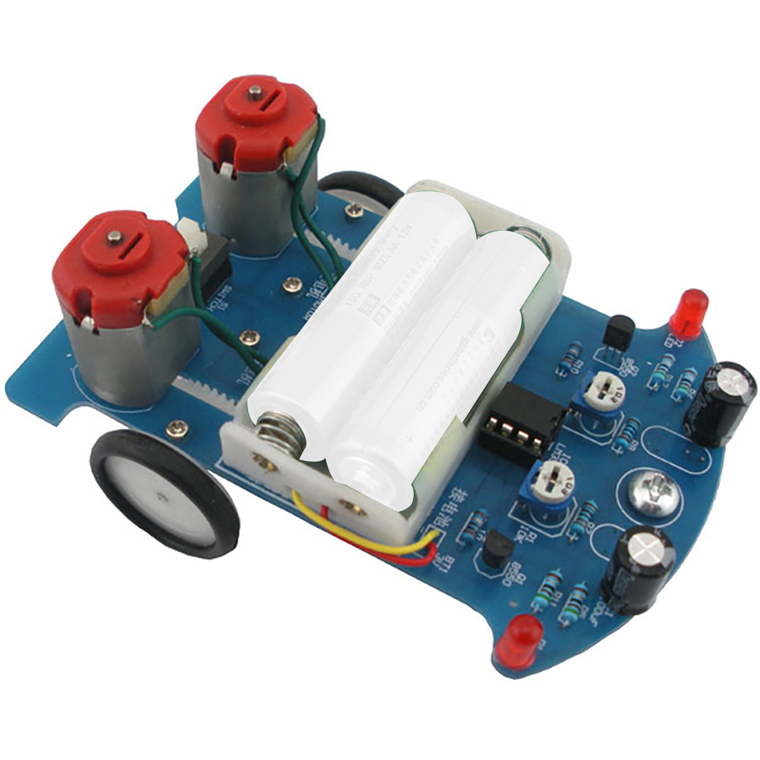
Feichao DIY Kit D2-5 Intelligent Tracking Line Car Truck Suit Motor Electronic Assembly Smart Patrol Smart Automobile Accessories
Specification:
Model: D2-5
Name: D2-5 Intelligent Tracking Car DIY Kit
PCB Size:104*72*1.6mm
Installation dimension:104*72*55mm
Work Voltage:3V
Package Includes:
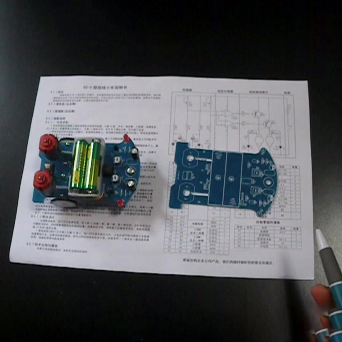
D2-5 Intelligent Tracking Line Car
NOTE:it is not includes the battery, the picture is only for reference demonstration effect.
It not welding
Assembly instructions:
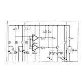
Circuit assembly:
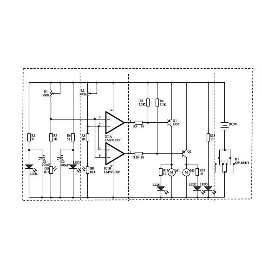
1. According to the circuit diagram and the identifier on the circuit board, the color ring resistor, 8-pin IC holder, switch, potentiometer, triode, electrolytic capacitor,
The φ5.0 LED is soldered to the board, paying attention to the direction of the IC holder. In addition, for the convenience of debugging, the chip is not installed.
2. Attach the battery box to the circuit board according to the diagram on the circuit board. The positive and negative poles of the battery box lead are red line +, and the two lead wires of the battery box are soldered to the corresponding position of the board.
3. With the front side of the board facing up, the support bolt of the universal wheel is inserted into the hole, the nut screwed into the universal wheel is tightened, and finally the universal wheel is mounted and tightened.
4. With the bottom of the board facing up, solder the φ5.0 LED (white hair red) and the photoresistor to the board according to the mark on the board. The LED and the photoresistor are required to be about 5 mm away from the spherical surface of the universal wheel.
5. Put two AA batteries in the battery box and press the switch. At this time, two φ5.0 LEDs (white hair red) should be illuminated. If it does not emit light, the positive and negative LEDs of the LED may be reversed. The negative pole is reversed. After the debugging is successful, the power supply is disconnected for use.
2. Mechanical parts assembly
1. Install four spacers on the board. The function of the gasket is to increase the gap between the axle and the circuit board so that the gear mounted on the shaft has sufficient space for rotation. First insert a M2.2*8 screw from the front of the board into the mounting hole, put a gasket from the back of the board on the screw, clamp the washer with small pliers, and turn the screw with a small screwdriver until the end of the gasket Close to the circuit board, this one gasket is installed, and the remaining three gaskets are installed by the above method.
2. Pass a steel shaft through the center hole of the wheel. Note that the direction is inserted from the side of the wheel with the raised bushing. It is preferred that the steel shaft is inserted flush with the smooth side of the wheel.
3. Put a three-way bushing into the steel shaft, close to the wheel, then put a gasket into the steel shaft, next to the three-way bushing. After loading it, push the three-way bushing and it should be flexible. Otherwise increase the gap between them appropriately.
4. Place a gear into the steel shaft and place it in the center of the steel shaft. Then a three-way bushing is placed over the end of the steel shaft so that the wheel assembly on one side of the car is ready. Hold the wheel with your hand and keep the steel shaft level. Adjust the position of the end tee bushing on the steel shaft. The gear on the steel shaft should just fall into the gear groove. Otherwise, adjust the gear position until it meets the requirements. Most of the two three-way bushings on the steel shaft are put into the protruding portions of the screws of the fixing washers, and tightened with small screwdrivers, so that the wheel components on one side are installed. Install the wheel assembly on the other side in the same way.
5. Insert a screw into the motor shaft, and then thread the screw out of the motor mounting hole on the front of the board. Secure the motor from the corresponding hole on the back of the board with two small screws. Note that the motor has a terminal side forward. After the connecting wires are divided into two sections, the upper tin is respectively soldered to the two terminals of the motor, and the other end of the wires is soldered to the corresponding mounting position of the motor. If the motor is found to be reversed when power is on, just change the position of the wire at the motor terminal.
3 overall debugging
1. Test the drive circuit, press the switch to turn on the power, connect the 1st, 7th, and 4th pins of the 8-pin IC. At this time, the wheel should rotate toward the front. Otherwise, the wiring position of the motor needs to be changed. Do not turn, please check whether the triode is soldered and the base resistance (10 ohms) is correct.
2. After power off, insert the LM393 chip into the 8-pin IC holder, and pay attention to determine the direction first. Adjusting the potentiometer after power-on allows the car to walk on the black line. The manual is attached to the test runway. You can also request an electronic version from the dealer, or use a 1.5 cm to 2 cm wide black tape, insulating tape, etc. as a runway.


Email:yxy@xt-xinte.com
Wechat:15012645226
Microsoft teams: 13640955802


No related record found